Overview
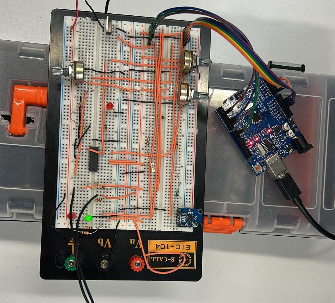
A drone or a levelling platform needs to know when it is tilting too far. Framed as a product for a client, this prototype measures lateral tilt with an accelerometer, conditions the signal with op-amps and reacts past a threshold: an Arduino switches on a motor and a warning LED, while a second, independent circuit lights a red alarm even if the microcontroller fails. Calibrated in LabVIEW, it met the specification’s targets for range, resolution, accuracy and bandwidth.
The specification asked for a measuring range of ±1.5 g, a resolution of 5 mg, a 10 Hz low-pass filter so that the motor’s vibration does not disturb the reading, an action threshold of 0.8 g, and a red alarm LED that works even if the microcontroller fails.
System design
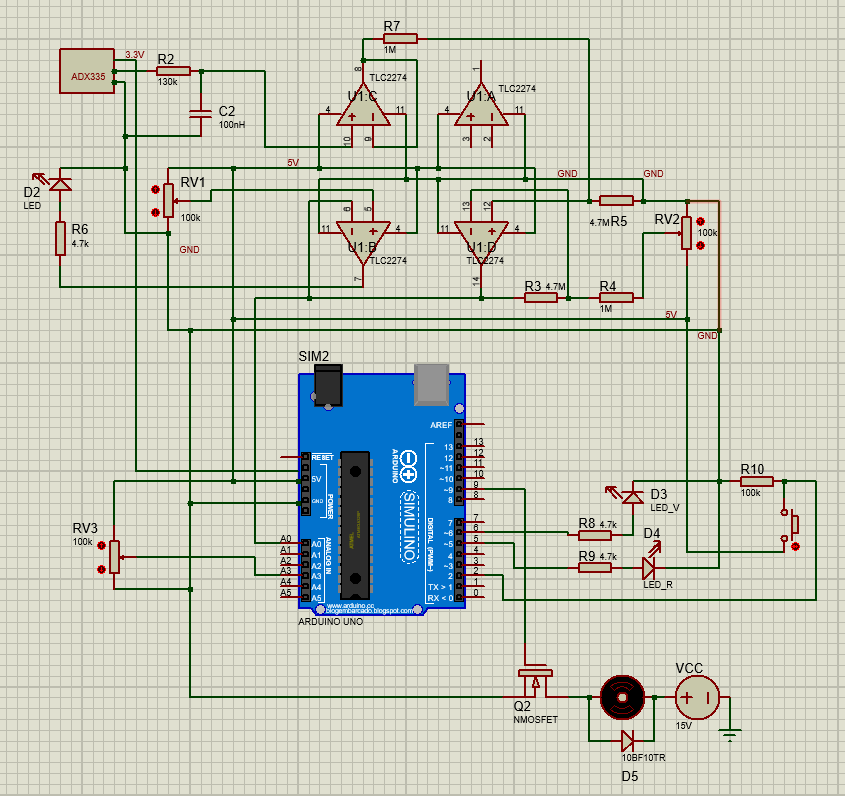
We split the circuit into functional blocks, so that each could be calculated, simulated and tested on its own before assembly.
- Sensor and filter. The ADXL335 accelerometer’s vertical-axis output goes through a first-order low-pass filter and a voltage follower that stops later stages from loading it.
- Gain and offset. A differential stage built with a TLC2274 rail-to-rail op-amp maps the sensor range onto the 0 to 5 V input of the Arduino, with 2.5 V at 0 g and a gain of 4.7.
- Redundant alarm. A second op-amp of the same chip, wired as a comparator, lights a red LED below the threshold without going through the microcontroller.
- Microcontroller. An Arduino UNO reads the conditioned signal and a speed potentiometer, handles an on/off button and drives the LEDs and the motor.
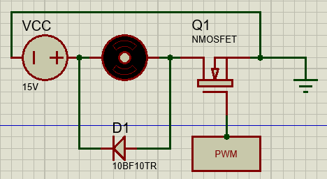
- Power stage. An IRF510 MOSFET switches a DC motor on a separate 15 V supply, driven by a PWM signal from the Arduino, with a 1N4001 diode across the motor.
The filter cut-off sets the resistor. With the 100 nF capacitor available:
The sensor already contains 32 kΩ in series, so the external resistor is 127 kΩ.
Measuring the sensor gave its real offset and sensitivity, (volts, with in g), and the gain and offset stage was calculated from these values instead of the datasheet’s nominal ones.
How it behaves
The prototype detects tilt; it does not correct it. When the vertical-axis acceleration drops below 0.8 g, the Arduino lights the red LED and switches the motor on, at a duty cycle set by hand with the potentiometer. Otherwise the green LED is on and the motor is off. The motor’s behaviour does not depend on how far past the threshold the board is tilted. The threshold in the code is 815 ADC counts, taken from the calibration, against 762 in theory.
Calibration and validation
A two-point calibration in LabVIEW, at +1 g and −1 g, gave the line used to place the 0.8 g threshold.
| Specification | Required | Measured |
|---|---|---|
| Measuring range | ±1.5 g | ±1.5 g |
| Resolution | 5 mg | 3.19 mg |
| Accuracy | 0.03 g | ±0.00314 g |
| Bandwidth (−3 dB) | 10 Hz | 9.82 Hz |
| Output at 0 g | 2.5 V | 2.5011 V |
| Action threshold | 0.8 g | 0.8 g |
| LED current | about 1 mA | 0.64 mA |
The LED current did not meet the specification. We raised the LED resistors to bring the circuit’s consumption down to 2.913 to 2.95 mA, and the LEDs became dimmer than required.
Problems found during development
The first readings made no sense and the Arduino saw no signal. Measuring the voltage at every node of the circuit led to the first voltage follower: the op-amp itself was faulty, and replacing it solved the problem. The on/off button did not seat well in the breadboard and made intermittent contact; soldering two wires to its legs fixed it. A last fix in the code made the button switch the system both on and off.
Cost and sustainability
A cost study was made for the components and materials used in the prototype, giving an approximate total of €64 at the course supplier’s prices. All the components are RoHS-compliant according to their datasheets, and the modular design makes the prototype easier to repair and reuse, in line with the WEEE directive.